Saturday, December 8, 2012

Tuesday, December 4, 2012

Revolution!

Well, a big day this last weekend. The control board works. I got it all wired and installed in the car. Hooked it up to 8 batteries, turned the key, pressed the accelerator and the wheels turned. Very, very exciting! I need to get a clamp ammeter and make sure the DC/DC converter is sending juice back into the 12V battery, which I think it is, but I am very happy everything is functioning as it should.

Here is a picture of the final control board layout installed in the car. It looks like a bad eighth grade science project, but I don't care, it works. I won't be showing my car at any car shows any time soon.

ERX Control board
I also took some video of the RPM and speedo gauges as I tested the system out in 1st gear.


This weekend I will hook up the rest of the 36 batteries, put the controller in more of a test mode, and maybe get the car down onto its wheels. If I am lucky, I will convince my wife to let me drive it out of the garage and into the driveway and then back again. She wants me to get more life insurance before I start testing the car on the street which makes sense. I also still need to send my charger in to get adjusted for the latest number of batteries I am using and the charge profile I want, then mount it and wire it into the system.

After that, I need to wire and mount my EV gauges and I have a bunch of car work to do. I have some electrical problems to solve with windshield wipers, brake lights, head lights, horn, need a new Left Fender, etc. I hope to upgrade to Integra brake calipers, rotors and pads and need to wire and mount my vacuum pump for the power brakes. Wow, so much more to do, but the EV system is just about done.

Monday, November 26, 2012

Christmas Countdown

The little elves have been busy in Santa's workshop making all kinds of cables and connections. The control board is pretty much finished. There is one fuse I want to find a better solution for, but it will work for now while in testing mode. Here are a few shots I took with a phone. Not as nice as the other photos on my blog, but they will due.

Control board sitting over the motor for a test fitting
The other half of the Anderson connector is not installed in this photo as well as a small fuse box.

High Voltage power section
Controller input on the far right with the contactors next to it. I have (4) 100 ohm, 10 watt resistors across the primary contactor for my pre-charge circuit. Next to the contactors is the main fuse at top and the shunt below.  Next to the fuse is the high voltage terminal block to send the high voltage to the DC-DC converter and the Amp hour counter/meter. The terminal block has a cover not seen here.

DC-DC Converter and 12V terminal block
Input and output of the DC-DC converter as well as the relay that switches the output on when the key is on. The 12V terminal block also has a cover not seen here.

Throttle box and cable
Here is the solution I came up with for connecting my throttle cable to the PB-6 throttle box. On the right I used a 2 inch piece of angle iron and made a slot for mounting the cable. I just need to tighten down the nuts on both sides to secure it. On the left I used a 1 1/2 inch piece of angle iron, drilled a couple holes for mounting it to the arm of the throttle box, then drilled a hole in the middle and a slot from the hole to the back side to get the end of the throttle cable attached. I will have to take a better picture of it this weekend so you can see what I did. Once again, it is not very pretty, but I think it will get the job done. I still need to throw some paint on them. I also need to get a spring to attach to the throttle arm as a backup in case of a failure of its spring.

If I could smell the finish line last week, then the plate is on the table and the fork and knife are in my hands now. Christmas should come early this weekend and hopefully Santa will be bringing me the EV GRIN!

Monday, November 19, 2012

Something smells good

Here is one picture from the last couple weeks. This is the rear battery boxes with the rear fuse and disconnect.

Rear battery boxes with fuse and disconnect
Yesterday I worked for about 9 hours on the control board. Mainly drilling the mounting holes for a couple items and some large holes for routing wiring as well as adding some grommets to protect the wiring.

I also made a couple pieces for the throttle cable assembly from angle iron. One piece was just a small bracket to mount to the PB-6 throttle arm, that had a hole for the throttle cable to go through, and the other was a mounting bracket to hold the cable in place. I had some trouble getting the cable in a good position to allow the throttle cable to move freely, but once I found the spot, the spring on the PB-6 easily drew the cable back. Now I have to find another spring to attach to the throttle arm as a backup in case the spring on the PB-6 breaks, or the throttle cable sticks some how. I have to find a small enough spring for the space I have, but also good tension, but not too much that it makes pressing the accelerator pedal tough.

I can smell the finish line, or at least the testing portion of the finish line. Next on the docket is wiring the control board, which I should be able to complete over Thanksgiving weekend. Then, connect all the batteries and start testing the system both on the jacks and then on the ground.

Friday, November 9, 2012

Connect the dots

I have made a bit more progress and am shooting for getting the car on the ground and testing by Thanksgiving. I will be working on it again this weekend and next weekend. Maybe even a day over the Thanksgiving holiday. Here are some photos of the latest work.

Added a grommet for the Positive Battery cable running to the rear of the car
Another angle - You can also see the flexible tubing to help protect the wire from debris
Flexible tubing for High voltage wire and a 1" clamp to hold it in place
Rear Fuse and disconnect location
Connection to front battery pack
Control board layout - Most of the mounting holes have been drilled
Installed RPM sensor on the tail end shaft of the Netgain Impulse 9" electric Motor
I have actually done more work than you see here, but forgot to take photos last weekend. I ran the negative cable to the rear of the car and installed another grommet for it to run through. I also crimped a couple more lugs on the wires and completed the rear Anderson disconnect assembly. This was my first attempt at an Anderson and it went smoothly. I bought new tires for the car since the ones I had were very worn and one was flat. This weekend I will finish up the negative cable installation by adding the flexible tubing and mounting it. I will also cut some more aluminum for the front battery racks and cut off a piece on the main rear battery box. After that, I plan to start wiring all the 12 Volt wiring for the control board. The following weekend should consist of double checking lots of stuff like mounting hardware, and wiring. Then, it will be time to connect all 44 of the batteries together, turn the key and see what happens.

Thursday, September 20, 2012

Rattle Rattle

Been a while since I have posted and I haven't worked on the car too much either. It has been very hot here and school has started as well as the second busiest time of the year for me at work. I am discouraged a bit because I am so close to having all the components hooked up and operating, but there is a minor issue. I am going to post a couple videos here and would love to get some comments but I need to explain them a bit.

I wanted to hook up some batteries to the controller and motor and do some tests in various gears, but didn't have tranny fluid. I filled the tranny with what I thought was the recommended fluid. At least thats what Pep Boys said. I also saw some posts online that it should take about 1.9 quarts. Well, Pep Boys was wrong and what I read online about fluid level was about the next model up of my vehicle. So, I had the wrong fluid, although probably not much different, and was a half quart shy. Here is a recording I made. The tranny is making noise. It is tough to hear because the brakes are rusty and are also making noise.


I was not happy about this at all. I talked to some guys and researched a little more. I got the correct fluid and filled it all the way up. I also removed the front wheels. One wheel is flat and the car had been sitting on it for a while so the balance of the wheels was probably causing issues. Here is the next video after making these changes.


A little bit of knocking at the higher rpms but tough to hear over the brakes. Much better than before though. In the first video the knocking only happened when I let off the throttle. This may be due to the flat tire and not quite full fluid level. In this video the knocking sound happens at the higher rpms, but does not make any sound when I let off the throttle. It is in 5th gear for this video. In the next video, I put it in 2nd gear and it is much smoother. I don't hear the knocking.


So, in 4th and 5th gear when the rpms get higher it starts to knock a bit. Does anyone think this is an alignment issue with the motor, adapter and input shaft? Could it be the old rusty brakes causing uneven amounts of resistance on either side and it causes the noises at higher rpms? Should I install all the batteries and put the car on the ground and get it rolling a bit to see how it acts with wheels and weight? Could it be that the tranny just needs some more time to get the oil in there and worked around? Any other thoughts? Please comment and let me know what you think.

Friday, August 24, 2012

Crimpin'

Not a huge update but more motion in the right direction. I have spent some time crimping the 2/0 cable to make various connectors on the control board as well as the connections to the motor.

Control board with 2/0 cable and lugs

Motor with 2/0 cable and lugs
The layout on the control board is not very straight, but that is what I needed to do to keep the contactors from being too close to each other. I may still add a piece of lexan or something in between them so the chance of touching the most positive and most negative side is smaller. I ran out of heat shrink so I did not finish the last lug on the motor, but more heat shrink is coming soon.

I hope to have the car in a test mode in 2 to 3 weeks. Wheels up tests and maybe wheels on the ground tests. That is very exciting.

Saturday, August 4, 2012

12V system test

A couple weeks ago I started piecing together my 12V system for starting the controller and turning on the contactors. I also learned how to crimp16awg wire to various connectors. I am still not great at it, but getting better on each one. I decided to hook up a few traction pack batteries to the whole system and test it out. Here is a video of that test. It is short and I rushed through it because the camera was out of space on the memory card. I will explain more below.


There is a bit of confusion right from the start. This test is mainly a test of the 12V system in the car which normally runs the lights, accessories, radio, etc. It now will also turn on my motor controller and the contactors which switch the traction pack voltage into the controller. The meter on the right says like 16V. This meter is connected to the traction pack which is the high voltage battery pack that moves the car. For this test I hooked up (5) 3.2 volt traction batteries to the controller so I could spin the wheels after the 12V system did what it was supposed to do by turning on the controller and contactors.

So I found the wire that used to feed the solenoid for the starter. This wire is the output of the on position of the key switch. Exactly what I need to make the car function just like a normal car would. The only thing I don't use is the start position on the key switch. If you saw my previous post you will see I have the inertia switch and an emergency stop button in series after the key switch. If either of these safety items are disengaged the controller and secondary contactor will not turn on. I used the inertia switch as an on/off for this test so I didn't have to run to turn the key and then run back to try and catch the pre-charge and primary contactor switching on. As soon as I hit the inertia switch in the video, 12V is fed to the secondary contactor and controller and they both turn on. This sends traction pack negative voltage to the controller and also starts pre-charging the controller because the pre-charge resistors are across the terminals of the primary contactor which allows the pack positive to reach the controller but at a low current. The controller has a pre-charge timer in it that you can set to whatever time you want. I set it to 5 seconds for this test. The time should be set based on the size of your pre-charge resistors. I have an email somewhere which says what resistors I should use. The only drawback to this system is if for some reason the pre-charge does not happen and the timer expires and switches on the primary contactor, there will be a huge inrush of current and could fry the controller. The simplest solution is to wire a volt meter across the input of the controller so when you turn the key, if the voltage does not start climbing, you can turn off the key before the timer expires. When I hit the inertia switch you see the meter start climbing in voltage. This is the pre-charge.

So back to the sequence of events. The controller's pre-charge timer expires and sends 12V to the primary contactor and it switches on which will now allow for full current to be drawn from the batteries. Next, I hit the potbox throttle and the tires start turning. I did not have an ammeter hooked up in the video, so no idea how many amps it was drawing. I had the batteries hooked up with 16awg wire. If you look closely at the blue wire on the left when I hit the throttle, you will see it move. I don't think that is from the motor or transmission. I think it is the current flying through that little wire. Those wires were fairly warm when I was done with a few tests. When it is wired properly it will have 2/0 gauge wire which is pretty think and can handle the current.

One last item which I am updating. I had to move a few things slightly on my control board due to the hood latch which I did not have installed previously. I realized it might cause some issues with the control board and so I put it back on and sure enough it was running into the secondary contactor. I moved everything towards the firewall by an inch or so and that cleared the space. Here is the updated picture of the location of the components on the control board.

New layout w/hood latch in place
Tomorrow I will drill mounting holes for the controller and DC/DC converter because I believe they are in their final resting positions. I will also do a test crimp or two on the 2/0 battery cable and lugs. I realize it is a $4 connector, but I want to make sure I do it right before trying to make all the connections I need.

Wednesday, July 11, 2012

Gaining Momentum

I am back after a couple weeks of R&R, but before we left on vacation I got to work on the car for a week. As usual, I got less done then hoped, but it really helped push the thought of getting the project done to the front of my mind. Travis and Naiche came over on the Saturday before my week of work on the project. They liked what I had done so far on the battery racks and boxes. One rack needs some better support, but I had a feeling it would anyways, so they confirmed that feeling. They also pelted me with questions about control board wiring and layout. They also really motivated me to try to get as much done in the week as I could and got me focused on finalizing my wiring diagram. The goal was to get a bunch of the wiring for the control board done and then test out the various components to ensure they were functioning properly and maybe spin the wheels with all the components hooked up.

This was a great plan, but I was still awaiting some wiring and hardware items in the mail as well as the 12Volt motorcycle battery I ordered. I worked on the high voltage wiring diagram and I also started on a 12V wiring diagram. Here are the latest "In Progress" versions.

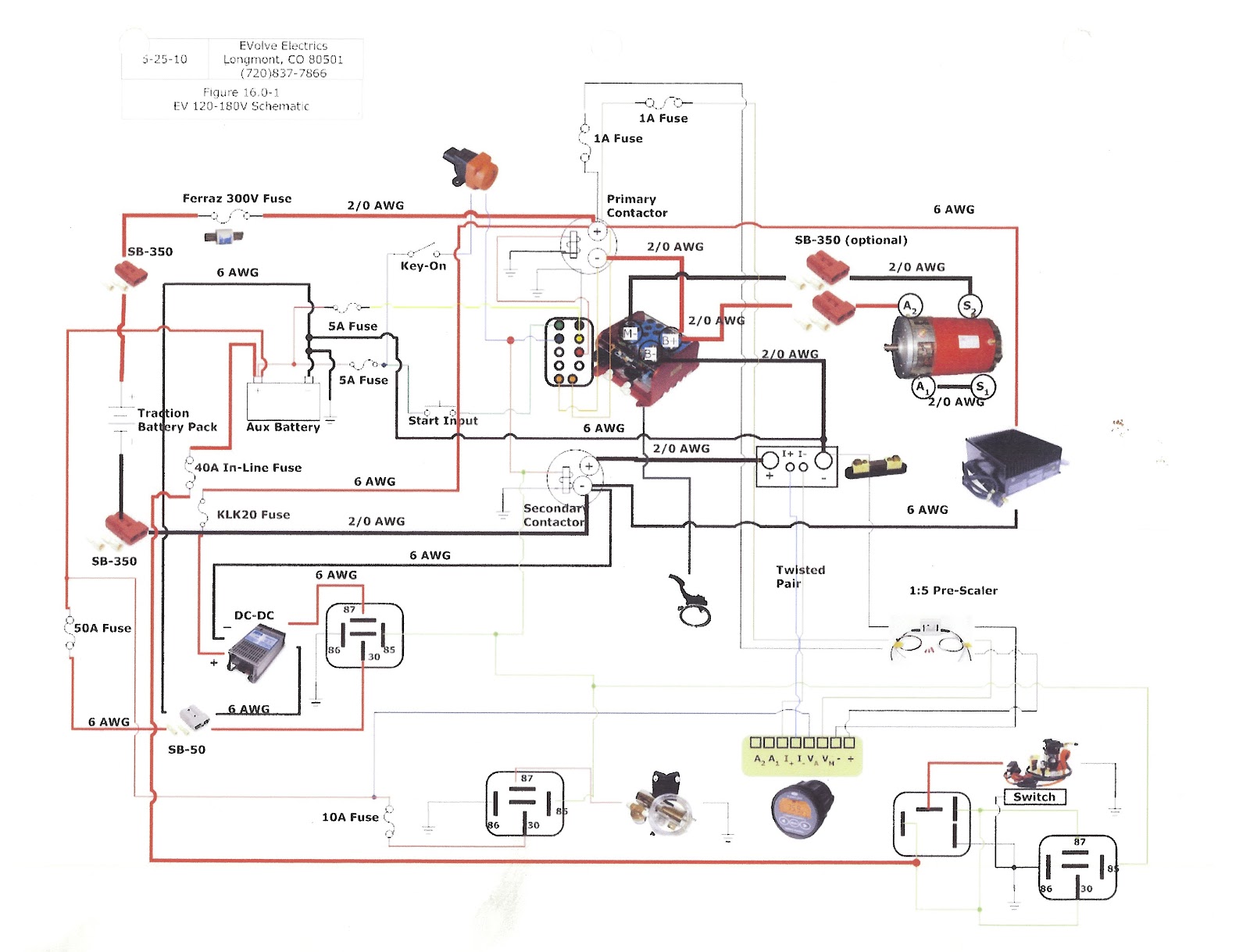
High Voltage Wiring Diagram Ver 7 - In Progress

12Volt Wiring Diagram Ver 2 - In Progress
I laid out the control and safety components on my component board to look for the best possible layout. Here is what I think will be the final layout of the components. There is blank space on the left side that will contain some terminal blocks for 12 volt and 140 volt distribution.

Component board layout
About mid-week I received my 12Volt motorcycle battery to run the car accessories, lights, blinkers, and the control components for the electric system. I made a little bracket out of some older aluminum which I had originally bent for my first attempt at battery boxes which didn't work. It was a perfect size for the 12V battery. I will probably just use zip ties to hold the battery in place.

12 Volt battery bracket

Motorcycle battery sitting on bracket
 At about the same time as the 12 Volt battery arriving, the ERX was moved into the garage. My landlord cleaned out the garage and agreed to let me put it in there for the time being. We actually got a notice from the city since it was sitting on jack stands in the driveway and listed as non-operable. The garage is going to help me a lot since now I can put my tools and parts in there and won't have to do so much prep and cleanup work every time I work on it. It also allows me to work in the evenings this summer when I get home from work and when it is not so hot outside.

The last task of the week was finishing the rear battery box install. I am 90% done with this task. I still need to tighten all the bolts. I had to drill holes in my battery boxes for mounting, but needed to have the batteries in them to make sure the boxes were nice and snug up against the batteries before marking the location for the holes. It took some time with putting in the batteries, tightening up the boxes, climbing under the car, and marking the locations. Then taking out the batteries, drilling, checking, drilling more, checking again, and finally putting the batteries back in and putting all the bolts in place. Here are a few shots of the work as it progressed.


Ahhh Happiness
So, I did not do much with the component board section, other than getting my wiring diagram in better shape and laying out how I think the components will fit on the board, but I accomplished other things that needed to be done and feel pretty good about the progress.

Next, I will try to borrow a heavy duty crimper for the 2/0 battery cable, so I can start to make some connectors for the batteries and the control board. I would also like to start adding the spade connectors to my component wiring and hook some items up and check their functionality with other components in the system.

Wednesday, June 6, 2012

Battery boxes and racks

I've moved a few millimeters forward lately. This post will have a bunch of pictures of some test fittings of the batteries in the front battery racks and also some more shots of the hatch area of the car where the battery boxes will go. I cut a few pieces of aluminum to put under the batteries and on the ends. The ones underneath will help give a nice flat surface for the batteries to sit on since I have some bolt heads underneath the racks which stick up a bit. It will also protect the bottoms of the batteries if debris somehow gets kicked up underneath them. The end plates are there because I will be strapping the batteries together to help protect against swelling in the event of an over charge. From everything I have read, there does not seem to be a problem with swelling at this point as long as you stop the charge at around 3.6 Volts per cell average, but if a cell got out of line from the others, as far as voltage, then it could over charge and swell up. Early on, I will be checking the cells after charge and after use quite often, but after a while it will probably only be once a month or so.

Bumper rack with (8) TS 160AH batteries

Firewall rack with (8) TS 160AH batteries

Both racks loaded up

Reverse angle with Control board sitting where it will be mounted over the motor
The next set of photos is in the hatch area. I finished painting the angle iron frame that the battery boxes will be hanging from, and have put them in place for a test fitting. I spent last weekend looking at what I need as far as hardware to bolt everything in place and making a big purchase list. I will be using a bunch of 1/4-20 Stainless Steel bolts and nuts, along with Nordlock washers. I am also buying a few M6 and M8 bolts for various areas where I can use the existing mounting points on the car.

Battery box frames in place

Added interior plastic to wheel well area

Note in the above picture the black plastic interior pieces. I got these off of a CRX forum a few months ago. Someone wrecked their car and was parting it out. My interior is actually blue, but I am ok with the black in the hatch area. I am still missing the piece on the back wall that covers the tail lights, so I will have to scour the net some more. It sure beats going to the local pick-a-part every weekend.

The next big issue is to look at the 12 volt wiring diagrams for the car and start to figure out what all the connectors are that are just hanging in the engine compartment. I didn't label them when we took the engine out and am kicking my self now. I won't need most of them, but I need the starter signal and there was some creative DIY wiring for a couple items that I need to figure out and replace.

Also, a couple guys are planning on coming over on the 16th to look at my progress and give me their thoughts before I head into a full week of work on the car. I am excited about that week, because I can knock out a bunch more things on my To Do list. Hoping to do a bunch of work on the control board and the original 12 volt system in the car.

Tuesday, May 8, 2012

Updated Wiring Diagram

I have updated my High Voltage wiring diagram and am posting it here for people to check out. Please let me know if you see any problems.


I have done a few things since my last post, but not a lot. April is a very busy month for me at work. I did some more work on the frames for the battery boxes, as well as did a trial fitting of the control board. I need to order some more hardware to secure it properly.


The month of May I should be able to get a few days in of work, and mostly will be trying to figure out details of hardware I need and make a plan for the big week in June that I will spend the whole week working on the car.

Friday, March 16, 2012

Wiring Diagram

I am posting the wiring diagram I received from Evolve Electrics, and one that I am creating as well to simplify it a bit. The Evolve diagram looks good and is complete, but a little overwhelming to look at, so I thought I would seperate the High Voltage wiring into its own diagram and the 12V system on its own. So far I only have the high voltage one done and am still looking for advice on if it looks correct and I have things located properly.

The first one is the diagram I got from Evolve. I do not have the Netgain controller that is pictured, so some of the wiring on here is not needed for my setup. I will also need to modify some of it to work with my controller.
Evolve Electrics Wiring diagram

 This next one is the high voltage diagram I created to simplify the wiring for myself. Let me know if you see any problems with what I have here.
HV wiring diagram - Work in progress - DO NOT USE!

Thursday, March 15, 2012

Painting, Drilling, odds and ends

I have finished the painting on the front battery racks and have begun the process of figuring out the mounting of the rear battery boxes. Here are some shots of the finished battery racks.
This rack will be mounted to the firewall and will hold (8) TS 160AH batteries
This rack will be mounted in the bumper area and will also hold (8) TS 160AH batteries

Quite some time ago, my buddy James made two angle iron frames to go around the holes I cut in the hatch floor. We also cut  and bent a bunch of aluminum for the battery boxes which will hang from the frame. I have also cut a couple pieces of steel to help stiffen the hatch floor around the frame so the boxes don't just drop out of the car if I hit a bump or hit the brakes hard. These boxes will hold the remaining cells. One will hold 20 and the other will hold 8. If you are playing along, that is a total of 44 batteries at 3.2V/cell and a total pack voltage of 140.8 volts. This is a 22 Kilowatt pack which should get me about 65+ miles of range at 60mph. I do not plan on pushing them that far because it will significantly reduce the life of the cells. My commute is 22 miles one way and I can charge at work, so I will only be using about 40% of the pack at a time on a regular basis. I recently assembled the battery boxes and took some photos.
Rear most battery box which holds (8) TS 160AH batteries
As you can see, my boxes are a bit different than what many people have done. The batteries stick out of the top by a couple inches. I designed it this way for a couple reasons. The boxes would hang too low and cause clearance issues if I set the batteries all the way in them. I am still concerned about this box since it is the closest to the back of the car and whether it may scrape going in or out of a steep driveway. The other thing it does is makes it a little easier to take a cell out if I need to test it or replace it. I am hoping I will not have to do this at all, but that was the idea. Many people cover their boxes which I think is a hold over from the lead acid days, or if they live in a very cold climate, it helps with keeping the cells warm. These cells only vent in an over charge situation and I have designed my charging system to avoid that as much as possible. Also, I live in SoCal, so the temperature shouldn't really be a problem. I will add some sort of strapping over the batteries to keep them in the boxes in the event of an accident. Here are some shots of the large battery box. It will weigh in at over 250 lbs.
Bottom of large battery box - 24 screws and nylon lock nuts

Top view of large battery box

Batteries have found their home

A nice yellow glow of happiness in their new home
I forgot to take a picture, but over the top of the screw heads at the bottom of the boxes, I have a couple pieces of aluminum to make a nice flat surface for all the batteries to sit on. You can see them in the above picture on the left side.

Over the next couple weeks I hope to finish the drilling and painting of the battery box frames and get those installed in the car along with the front battery racks. After that I think I will start working on mounting the component board and figuring out the layout of the components which will be on the component board. I think I still have 250+ hours of work ahead of me, but one by one I am getting things crossed off the giant to do list.