Monday, November 26, 2012

Christmas Countdown

The little elves have been busy in Santa's workshop making all kinds of cables and connections. The control board is pretty much finished. There is one fuse I want to find a better solution for, but it will work for now while in testing mode. Here are a few shots I took with a phone. Not as nice as the other photos on my blog, but they will due.

Control board sitting over the motor for a test fitting
The other half of the Anderson connector is not installed in this photo as well as a small fuse box.
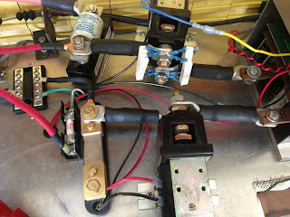
High Voltage power section
Controller input on the far right with the contactors next to it. I have (4) 100 ohm, 10 watt resistors across the primary contactor for my pre-charge circuit. Next to the contactors is the main fuse at top and the shunt below.  Next to the fuse is the high voltage terminal block to send the high voltage to the DC-DC converter and the Amp hour counter/meter. The terminal block has a cover not seen here.

DC-DC Converter and 12V terminal block
Input and output of the DC-DC converter as well as the relay that switches the output on when the key is on. The 12V terminal block also has a cover not seen here.

Throttle box and cable
Here is the solution I came up with for connecting my throttle cable to the PB-6 throttle box. On the right I used a 2 inch piece of angle iron and made a slot for mounting the cable. I just need to tighten down the nuts on both sides to secure it. On the left I used a 1 1/2 inch piece of angle iron, drilled a couple holes for mounting it to the arm of the throttle box, then drilled a hole in the middle and a slot from the hole to the back side to get the end of the throttle cable attached. I will have to take a better picture of it this weekend so you can see what I did. Once again, it is not very pretty, but I think it will get the job done. I still need to throw some paint on them. I also need to get a spring to attach to the throttle arm as a backup in case of a failure of its spring.

If I could smell the finish line last week, then the plate is on the table and the fork and knife are in my hands now. Christmas should come early this weekend and hopefully Santa will be bringing me the EV GRIN!

Monday, November 19, 2012

Something smells good

Here is one picture from the last couple weeks. This is the rear battery boxes with the rear fuse and disconnect.

Rear battery boxes with fuse and disconnect
Yesterday I worked for about 9 hours on the control board. Mainly drilling the mounting holes for a couple items and some large holes for routing wiring as well as adding some grommets to protect the wiring.

I also made a couple pieces for the throttle cable assembly from angle iron. One piece was just a small bracket to mount to the PB-6 throttle arm, that had a hole for the throttle cable to go through, and the other was a mounting bracket to hold the cable in place. I had some trouble getting the cable in a good position to allow the throttle cable to move freely, but once I found the spot, the spring on the PB-6 easily drew the cable back. Now I have to find another spring to attach to the throttle arm as a backup in case the spring on the PB-6 breaks, or the throttle cable sticks some how. I have to find a small enough spring for the space I have, but also good tension, but not too much that it makes pressing the accelerator pedal tough.

I can smell the finish line, or at least the testing portion of the finish line. Next on the docket is wiring the control board, which I should be able to complete over Thanksgiving weekend. Then, connect all the batteries and start testing the system both on the jacks and then on the ground.

Friday, November 9, 2012

Connect the dots

I have made a bit more progress and am shooting for getting the car on the ground and testing by Thanksgiving. I will be working on it again this weekend and next weekend. Maybe even a day over the Thanksgiving holiday. Here are some photos of the latest work.

Added a grommet for the Positive Battery cable running to the rear of the car
Another angle - You can also see the flexible tubing to help protect the wire from debris
Flexible tubing for High voltage wire and a 1" clamp to hold it in place
Rear Fuse and disconnect location
Connection to front battery pack
Control board layout - Most of the mounting holes have been drilled
Installed RPM sensor on the tail end shaft of the Netgain Impulse 9" electric Motor
I have actually done more work than you see here, but forgot to take photos last weekend. I ran the negative cable to the rear of the car and installed another grommet for it to run through. I also crimped a couple more lugs on the wires and completed the rear Anderson disconnect assembly. This was my first attempt at an Anderson and it went smoothly. I bought new tires for the car since the ones I had were very worn and one was flat. This weekend I will finish up the negative cable installation by adding the flexible tubing and mounting it. I will also cut some more aluminum for the front battery racks and cut off a piece on the main rear battery box. After that, I plan to start wiring all the 12 Volt wiring for the control board. The following weekend should consist of double checking lots of stuff like mounting hardware, and wiring. Then, it will be time to connect all 44 of the batteries together, turn the key and see what happens.